Now that the painting, decaling, and weathering was completed on my F-14A, I could bring everything together in a final assembly. With plans in mind for taking this model to various shows and competitions, I left several parts unglued and detachable for easier transport.
The canopy, fuel tanks, stabilizers gear and wings are all detachable and held in place with either friction on small magnets. This meant that final construction of this project went pretty smoothly and without issue.
With the primary paintwork done on the F-14, I could finally seal everything up with a GX100 gloss varnish. The decals I chose for this project was the Furball Aero-Designs part II set. I’ve been wanting to try out a Furball set for white a while now and was pleased with how the performed, having both excellent detail and setting good characteristics.
For this build I did opt to try to sand the excess lip away created by the decals. I went about this by spraying on subsequent layers of gloss varnish before sanding over the decal. I don’t do this for every build as it can be somewhat time consuming but for subjects that have large, prominent decals, I think that the additional time spent here is worth it. I started out with 6000 grit sanding sponges before moving on up to 8000.
Weathering
With the decals squared away, I turned my attention to the weathering. Initially I had thought to keep weathering minimal and try to complete the process as quickly as possible with the finish line so close. After taking a day to think things over, I decided that trying to rush things right at the end was not the right decision.
With the model currently in a gloss coat, I settled on starting the weathering with some oil streaking effects. I decided to start on the underside of the model where mistakes would be less obvious, and where the real subject would be more likely to build up dirt and grime.
I started the oil effects by brushing slightly diluted dark brown oil paint in the areas I wanted streaks to occur. I allowed the oils to dry for a few minutes before dragging a fan brush moistened with oil thinner over top the streaks. I particulary like this technique at the start of weathering as this effect serves as an anchor for future work.
I continued this effect throughout the rest of the model, although I opted to limit it somewhat on the upper surfaces of the aircraft as I felt that overly prevalent streaks would be distracting and overwhelm the viewer. Although it took a bit to get the look right, I’m fairly happy with how it turned out as this was a good start to replicating a heavily worn Tomcat.
I then chose to seal the oil in a satin varnish. This was required because the oils are very fragile to damage and alteration. In fact, even after dry for several days, they never really dry off completely and as such need to be sealed underneath a varnish to completely fix them into place. I chose a satin varnish as well because there were some subsequent effects that I wanted to try out that would perform better on top of a satin finish rather than a gloss.
The first effect I applied was a dark grey pinwash over the models panel lines. While the panel lines were somewhat subject to a wash when the black ink layer was applied, I found that the effect had been diminished somewhat and I wanted to bring out the prominence of the lines again. To do this, I made up a dark grey oil colour and applied it sparingly over the model’s various panel lines, and was cleaned up with a paper towel.
Following the panel line wash, I then got back to further streaking effects, this time with pastels. I had never used pastels before as a weathering medium, however I saw them used in an interesting way to re-create subtle streaking effects that I thought was worth trying to replicate. I first used my hobby knife to scrape off some of the pastels before loading up a silicone shaper tool with clumps of the pastels. I would then drag the shaper over top the model which would create a subtle streaking effect. One thing that I like about this approach is that the pastels take a long time to build up and it’s easy to not take things too far. It’s a very forgiving technique.
I largely used this process on the wings and again on the underside of the fuselage, this time adding volume to the earlier oil streaking effects. The technique works particularly well when the top of the panel is taped off, creating a very nice contrast with the unaffected surface.
After completing work with the pastels I then moved back to oils for some select weathering in specific places. The first place I focused on was the hinges for the flaps and ailerons. I had done some colour modulation in this area and felt that it could use some more work. I applied some minimally diluted dark brown oil paint to the hinge before working over it with a larger brush. I took care to wipe away any grime that had moved up the wing as I felt that this area would not have gotten as dirty.
Next, my attention turned to the anti slip surfaces on top of the intakes. I had chosen to used the included decals for this area and as such they were not looking weathered at all. To fix this, I again utilized oils and faded them around the edges to recreate dust and dirt buildup that had accumulated due to foot traffic.
The final weathering effect that I applied to the model was the anti-corrosion paint touchups that were applied by crews while on deployments. These touchups are very prominent on weathered Tomcats and I wanted to recreate them on my build. I opted to create this effect with two methods, with metal templates and free hand airbrushing. I started applying paint through the template to get a good feel for how the airbrush was spraying prior to trying to freehand onto the model. I think that this approach turned out well as it recreated fairly accurately how paint touchups were applied to the real life aircraft.
With this final step in the weathering process completed, I sealed my work in a matte varnish. With this major stage complete, I was able to move on the penultimate steps before completing the build!
I have to admit, I’ve been looking forward to this phase of the build for some time now. The Tomcat’s TPS scheme weathers in a very interesting way and painting it was going to be a blast.
As with all my models, this phase started with Mr. Surfacer 1500 black. I did pickup some seams in the primer, so I sanded them down and resprayed some more Mr. Surfacer. After here however, I took a very different direction in the painting of this model. I decided to use the Layered ink patina technique popularized by modeller Kris Sieber (@Luftraum72) instead of my standard marbling/preshading approach. What this called for was the application of solid colour over top the primer before stippling liquidex inks over the paint.
Few paints spray as smoothly as SMS and it almost felt criminal covering these layers up. To start, I brushed X-20 Acrylic thinner over top the paint in preparation of the Liquidex Titanium White being brushed over top. After the correct about of ink had been applied I quickly began stippling the ink with a coarse stippling brush. It’s important to work fast here, the ink drys quickly and once it does it’s set in its pattern. You can add more x-20 onto the dried ink to activate it again however this is a hit and miss technique and should not be relied upon.
Following this layer, I diverged from the established process and wanted to re-entroduce to panel line variation in the finish. To do this, I masked off some sections and painted them in diluted grey, black, brown and white. It’s important not to go overboard in this step as it will take away some the contrast from the white acrylic ink. Following the panel line variation layer, I apply an approximately 60% opacity layer of the blue grey colour. This is to tint the section back towards the desired colour tone. The last step is to apply Liquidex Carbon Black ink and stipple it in the same manner as the titanium white. The carbon black is allowed to dry before it is almost entirely wiped away with X-20 thinner. I mist one final coat of blue grey before completing the specific section I am working on.
Below you can see various parts all at different stages of this gathering process. The Fuselage has been painted in Blue grey with no colour modulation. The wing has been stippled with white ink, had specific panels shaded, and the 60% opacity grey layer added. The stabilizer is complete with the Black ink and the final grey mist layer. This photo does a really good job at demonstrating the stages of this weathering process.
With the sub assemblies well on their way, I got to work painting the main fuselage. I had painted this section here and there whenever I had some spare Blue grey in my airbrush but eventually the time came to finish this task of the build.
As always, the SMS paint went on buttery smooth and provided a nice base for further work with the acrylic inks. I did however, chose to deviate from the process followed during the wing and stabilizer painting and chose to highlight some panels prior to applying the white ink. I did this because I felt that shading after the ink was applied was covering it up too much and wanted to see if shading specific panels would still be visible after several ink applications and shading.
Following the panel variation effect, I applied the first layer of Liquidex Titanium white, as seen in the earlier steps, then a layer of colour modulation over top. I decided to introduce a new process at this point, adding a random panel line pre-shade with a dark brown/black colour. I continued with the pre-shading, adding some SMS Gunship Grey in order to highlight select pannels.
After the preshading was completed, work could move on to blending the layers together. First, I needed to seal in the previous work with a Lacquer satin varnish. This step is crucial because further inks will be applied and if done without the varnish they will begin to re-activate the underlying Titanium White layer.
With the Titanium White ink sealed in, I then got to work applying a 2/1 mixture of Carbon Black and Titanium White ink in the same manner of the initial layer (stippled on with a stiff brush, over top X-20A). After the ink has had a chance to dry, A paper towel moistened with X-20A is rubbed over the surface, removing the majority of the black in, with it remaining in very limited parts of the surface.
At this stage, the Model is very near to its finished colour however some final tuning is required to get the look that I’m after. If left in its current state, the model would be somewhat over weathered. To remedy this, I Apply a very diluted layer of more SMS Blue Grey in order to achieve the final colour of the F-14. I am essentially slowly blending everything together in the same shade that I started this process with. The end result is a highly realistic TPS finish that has already been weathered somewhat.
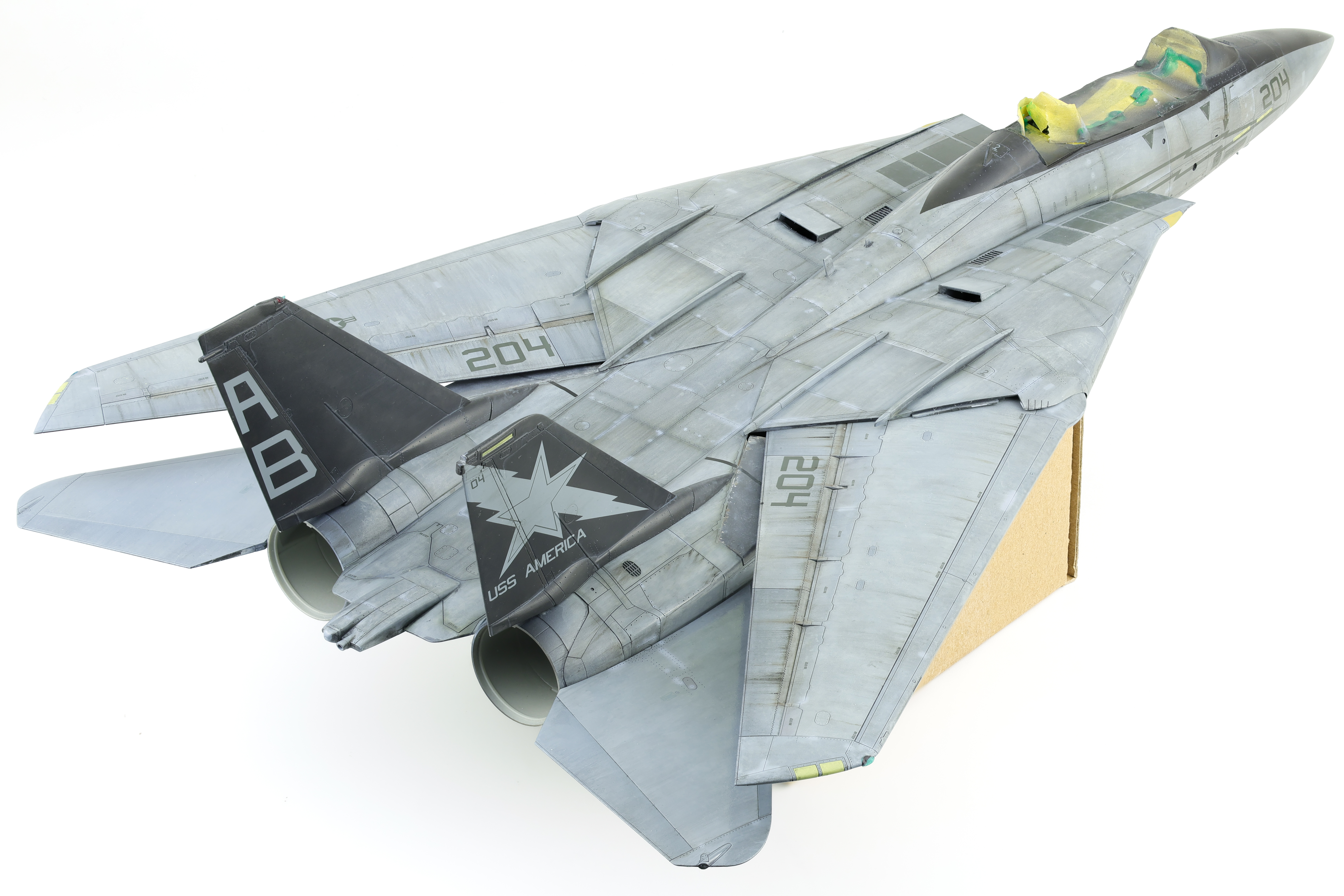
After completing the final Blue Grey blend coat, I could turn my attention to the scheme elements for this specific F-14. The specific aircraft I’m building was a VF-33 bird in the squadron’s farewell livery, featuring black tails and a black cockpit accent. This necessitated some masking as I wanted to paint these section prior to spraying the gloss coat. This process was pretty straightforward and just required some tedious masking and minor colour variation effects.
With the completion of the primary paintwork, this portion of the build was complete! I then gloss coated the model before starting the decals.
With the preliminary work on the cockpit and gear finished, I could turn my attention to bringing these elements together and completing the major construction for the F-14.
The first thing I did was swap out the identification lights molded into the kit plastic. These are fairly basic and the Quickboost replacements I got for this project are definitely an improvement. With all that said, it was a huge pain to replace these with the aftermarket set and I probably wouldn’t want to do this again. These accessories required quite a bit of cutting and sanding followed by polishing to ensure that they were as clear as possible. The section in the kit plastic must be cut out and the Quickboost part must be cut so that it fits in place. Then, you have to sand down the joint so that there is not obvious seam, all the while taking care that you don’t scratch where the actual light is. Knowing that this was meant to stay clear on the final result, I used a chrome marker to paint the back of the clear part before polishing it with Tamiya polishing compound. I’ll admit it looks good, but the time wasn’t worth it for me.
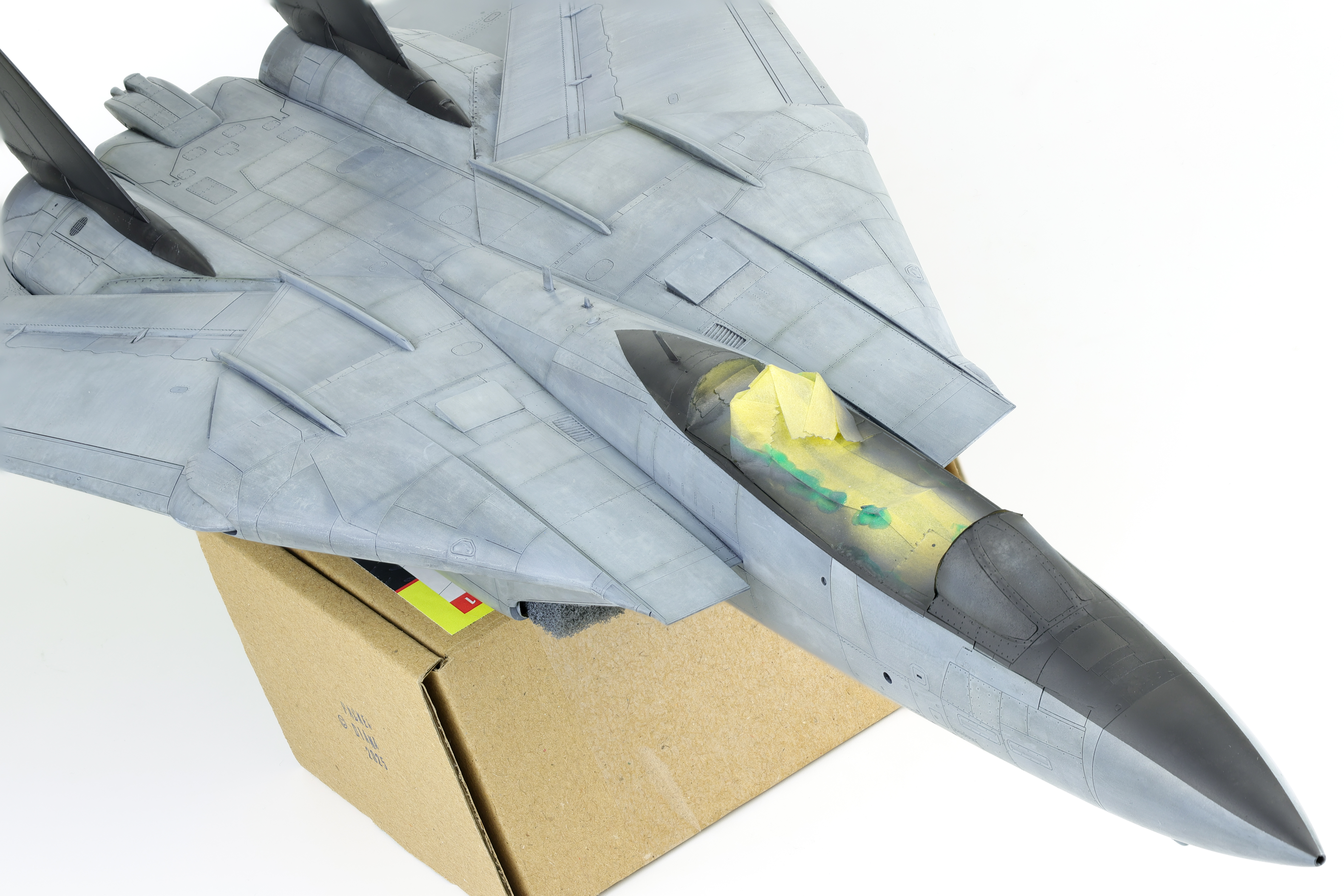
After this was done, I got to work on the intakes. I’ll have next to no ability to paint these when installed onto the model so that means they’ll have to be completed before installation. As per the instructions and reference photos, these are gloss white and the fuselage colour. Tamiya is kind enough to provide masks for this to be recreated and I was fairly happy with the end result using them. The fuselage colour I would be using was SMS PL60 Blue grey FS35237. I put down a coat of gloss white, applied the mask, then added the Blue grey.
I also took this time to weather the Blue grey as it was common for dirt to accumulate in this area due to inspections by maintainers. I did this with a dark brown oil paint, and slowly feathered it onto the surface to create a restrained look. I then installed the main gear bays, the completed intakes and was able to seal everything up. It should be noted that the fit of the MCC gear bay was somewhat rough and it took a lot of work to ensure that a solid seal was being achieved around the kit parts. Furthermore, when cutting off the indicated section on the intakes to fit the MCC part, aim to cut 0.5-1mm shallow. Cutting as indicated will leave a significant gap between the MCC gear bay and the intakes.
Following the installation of the gear and intakes I joined the two fuselage halved together. I used to tape do this as I’ve never had a ton of luck using clamps. Following some filling and sanding (especially around the nav light location) I attached the forward fuselage. This section has excellent fit and creates an almost non-existent seam. I was also able to check that the gear fit properly into the installed gear bays. I’ll be keeping these detached during the painting process so that the bays can be masked up.
The next step was to complete the various sub assemblies before moving on to paint. This included the wings, stabilizers, pylons and canopy. This went together in typical Tamiya fashion and before I knew it this bird was ready for paint. This being a Tamiya kit, the fit was excellent. I decided to take advantage of this and opted to incorporate some magnets into various parts so that the model would be able to be partially disassembled after being completed. I stuck some tiny 1mm magnets inside the vertical stabs and the effect is practically invisible.
After six months on the bench, I’m quite happy with the end result on this one. This build faced a lot of challenges and problems to solve but never stopped being a fun build. It was incredibly satisfying to update this kit to a modern standard.
I finished the model in a standard flat finish, enjoy the completed build photos Below!